


Soluciones
La gama de negocios de construcción de caballos se extiende a todo el mundo y sirve a miles de clientes con productos, orientación técnica especializada en construcción, y somos testigos del reinicio de la marca china con ellos.
In recent years, FRP materials, especially CFRP materials, have been widely used in civil engineering. Although not as widely used as reinforced concrete structures, CFRP reinforced steel structures have also begun to be applied to bridges and housing construction.
1. Introduction
In recent years, FRP materials, especially CFRP materials, have been widely used in civil engineering. Although not as widely used as reinforced concrete structures, CFRP reinforced steel structures have also begun to be applied to bridges and housing construction. Research has also proved that CFRP can effectively improve the strength and stiffness of steel beams.
2. Laboratory research
In this study, 1 unreinforced steel beams and 7 CFRP plate reinforced steel beams were tested. CFRP plates with different lengths and thicknesses, different loading modes (including three-point bending and four-point bending) are used to obtain the effects of different parameters on the strength and stiffness of the strengthened steel beams.
2.1 specimen preparation
The I-shaped steel beams used are 1.2 m long, 127 mm in height, 76 mm in width, 7.6 mm in flange thickness, 4 mm in Web thickness, 275 MPa in design load and 205 GPa in elastic modulus. The thickness of CFRP plate used is 3mm or 6mm, and the elastic modulus is 210GPa. The structural adhesive is Sikadur one 31 of Sika Corporation and the shear modulus is 2.6GPa. In order to ensure the thickness of the adhesive layer is 1mm, the small glass beads with diameter of 1mm are mixed into the structural adhesive in proportion of 1%. After bonding to the steel beam, the plate will be maintained for more than 72 hours.
2.2 test method
The loading form is three point bending or four point bending, where the four point bending point is 300ram. Liang Jingkua is 1.1m. Loading speed is 0.05mm / sec. The deflection of the beam is measured by three potentiometers, and the specific placement is shown in Figure 1. In order to record the strain distribution at the bottom of the CFRP plate in the specimen of $305, seven 2 mm long strain gages Gl-G7 are longitudinally attached to the center line of the bottom of the CFRP plate, as shown in Figure 1. To measure the strain distribution in the span, three 5 mm long strain gauges are attached to the bottom of the upper flange, the middle of the web and the top of the lower flange, as shown in Figure 1. When the steel beam is locally unstable, it will stop loading.

3.Test results and discussion
3.1 strength
The load deflection curve of a non reinforced steel beam and 5 reinforced steel beams subjected to three point bending is shown in Figure 2. The load of 2 reinforced steel beams subjected to four point bending. The deflection curve is shown in Figure 3. It can be seen from the diagram that (a) the ultimate load increases with the increase of slab length. This is because the stress concentration at the end of the plate leads to the stripping failure of the CFRP plate, which makes the strength of the CFRP plate not give full play. The stress concentration decreases with the increase of the plate length; (b) When the CFRP plate instantaneously peels off the steel beam, the load on the beam also decreases rapidly. It can be seen from this that the strength of beams is enhanced by CFRP board.
For two specimens of the same length but different thickness, $305 and $305D, their maximum bearing capacity is 149.1kN and 112.1kN, respectively. It can be seen that the bearing capacity of S305 with a thickness of 3mm is higher than that of $305D with a thickness of 6mm. This is due to the increase of stress concentration at the end of the plate due to the thick plate, which makes the CFRP board easier to peel off.
3.2 stiffness
From the load deflection curves of figures 2 and 3, we can also see the influence of CFRP plates on the stiffness of steel beams. The stiffness of CFRP plate is not improved obviously before beam yielding. This is because the elastic modulus of CFRP used in the test is relatively low and the thickness of the plate is not large. Increasing the thickness can increase the stiffness of the beam, but also increase the stress concentration at the end of the plate. Fig. 4 shows the deflection comparison of the specimens subjected to three point bending under 70 third loading. It can be seen from the diagram that the length of the slab has no effect on the deflection of the middle span. Therefore, increasing the thickness of CFRP is an effective way to improve the stiffness of steel beams.

3.3 failure mode
The load-deflection curves shown in Figs. 2 and 3 show that all CFRP plates of the specimens are instantaneously peeled off the steel beam except $310. The specimens of $310 were destroyed due to the local instability of the steel beam because the plate was 1 m long and the stress concentration at the end of the plate was very small. The failure mode of other specimens is that the CFRP plate is completely stripped from the steel beam. Fig. 5 shows the specimen $304 after failure. It can be seen that the peeling surface is mainly at the interface between the steel beam and the structural adhesive.
3.4 maximum interfacial stress
The maximum interfacial shear stress, normal stress and principal stress of the strengthened steel beam under the action of maximum bearing capacity can be obtained from the analytical formula of De bearing capacity. Except for the failure of $310 caused by local instability, the maximum interfacial shear stress, normal stress and principal stress of other specimens are very close, and their dispersion coefficients are 4.25%, 5.30% and 2.89% respectively. These results confirm the reasonableness of the formula for calculating the maximum interfacial stress.
Conclusion
This paper introduces the static load test of steel beams strengthened with CFRP plates. The test results show that the ultimate bearing capacity of the strengthened steel beam increases with the increase of the length of the CFRP slab, but decreases with the increase of the thickness of the CFRP slab. Because the elastic modulus and thickness of CFRP plate are relatively small, the stiffness of the strengthened steel beam is not significantly improved. Except for $310, all specimens were stripped and destroyed by CFRP plates. The maximum interfacial stress of specimens under the maximum load calculated by the theoretical formula is very close, and the longitudinal strain recorded by the strain gauge coincides well with the theoretical strain. All these prove that the theoretical formula of Deng et al. L71 is reasonable.
Puede encontrar cualquier cosa que necesite, confíe en probar estos productos y encontrará la gran diferencia después de eso.

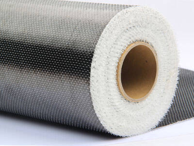
Tejido de fibra de carbono unidireccional de alta resistencia para refuerzo de compuesto de polímero reforzado con fibra (FRP).

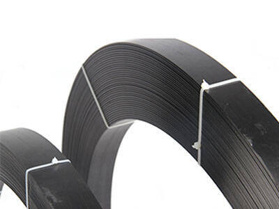
Lámina de fibra de carbono pultruída para reforzamiento de estructuras

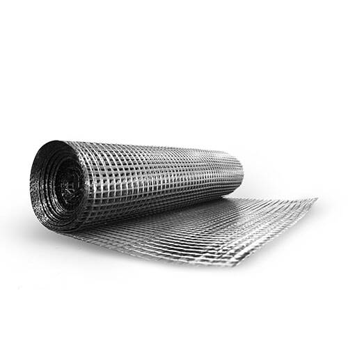
Placa / laminado / banda de polímero pretensado reforzado con fibra de carbono (CFRP) para la losa, refuerzo del haz
