


Soluciones
La gama de negocios de construcción de caballos se extiende a todo el mundo y sirve a miles de clientes con productos, orientación técnica especializada en construcción, y somos testigos del reinicio de la marca china con ellos.
The results of Strengthening Masonry Structure with carbon fiber fabric are mainly affected by the vertical normal stress, the ratio of height to width of masonry wall and the number of CFRP layers.
1. Introduction of masonry structure
The layout of masonry structure itself is relatively simple, and many buildings can not meet the functional requirements of modern buildings. In addition, due to the low tensile and shear strength of masonry structure, brittle failure is easy to occur, the ability of bearing horizontal load of the building is poor, the seismic capacity is weak, and the reliability of the structure is seriously reduced after long-term use.
Once a strong earthquake occurs, the seismic damage of brick masonry structure is often more serious, seismic reinforcement is very important. The traditional reinforcement method has a long construction period, occupying building space, consuming steel and difficult construction. Fiber reinforced composites (FRP) composite reinforcement is a new technology for masonry structures proposed in recent years. It can not only avoid the shortcomings of traditional reinforcement methods, but also not change the cross-section shape of components, high strength, high efficiency, light deadweight, convenient construction, corrosion resistance, wide application and other advantages. In this paper, based on the experimental study, the finite element software is used to analyze the stress of the masonry wall strengthened with carbon fiber fabric. After verifying the rationality of the model, the effects of stress ratio, height-width ratio and the number of carbon fiber fabric layers on the strengthening effect of masonry wall are discussed, and some useful conclusions are obtained.
2.Test situation
This test adopts a scale brick masonry wall. After bonding with carbon fiber fabric, seismic simulation test is carried out. The prototype of the model is a middle school dormitory building in Zaoqiang County, Hengshui City. The main research contents are to analyze the shear capacity and deformation behavior of brick masonry walls strengthened with carbon fiber fabric under the combined action of vertical axial force and horizontal repeated load.
2.1 Specimen parameters
Three masonry wall specimens were made in this test. The model size of the specimens was reduced to 1:2 according to the actual masonry wall. The thickness of the masonry wall specimen is 120 mm, the height is 1100 mm, the width is 1600 mm, and the aspect ratio is 0.688. The thickness of the seam is 10 mm. The reinforced concrete beams are connected to the masonry walls and lower parts. Masonry wall models are represented by "W10". Sample number and reinforcement plan are shown in Table 1.
The specimen number and reinforcement scheme
| Sample number | Reinforcement measures |
| W10M5 -1 | Unreinforced, used as contrast specimen |
| W10M5 -2 | Double side paste "X" type carbon fiber fabric, width 200 mm, anchorage fiber width 80 mm |
| W10M5 -3 | Double side paste "#" carbon fiber fabric, width 150 mm |
When the specimens are made, the masonry wall material is consistent with the actual project, using MU10 sintered brick, M5.0 cement mortar, the upper and lower beams are all C20 concrete; the reinforced CFRP is used high-strength grade II carbon fiber fabric; the mechanical properties of each material are shown in Table 2 to Table 3.
The performance index of carbon fiber fabric
| Tensile strength | Tensile elastic strength | Elongation | Bending stength | Tensile bond strength | Thinckeness | Weights |
| 3000 Mpa | 2.1*105Mpa | 1.15% | 626.7Mpa | 3.88Mpa | 0.111mm | 200g |
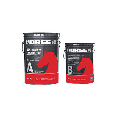
The performance index of structural bonding adhesive
| Tensile strength | Tensile elastic strength | Elongation | Bending stength | Compressive strength | Tensile bond strength |
| 41.5Mpa | 2868Mpa | 3.51% | 54Mpa | 72.5Mpa | 4.94Mpa |
3. Parameter analysis
3.1 Influence of vertical normal stress σ 0
When the ratio of height to width and the strength of masonry wall are fixed, the different vertical normal stress σ 0 will affect the form of masonry wall cracking, the sequence of various cracks and the cracking load of masonry wall. This section will study the effect of different vertical normal stresses on carbon fiber fabric-strengthened masonry walls under other conditions. The ratio of height to width of masonry wall is 0.6875, carbon fiber sheet is double-sided and single-layer. The material of masonry wall is identical to the test masonry wall. The vertical normal stress is 0.5 MPa, 1.0 MPa, 1.5 MPa, 2.0 MPa, 2.5 MPa, 3.0 MPa and 3.5 MPa, respectively. In front of the MU10 clay brick and M5.0 cement mortar, the compressive strength is 9.5 MPa and 8.7 MPa, respectively. The average formula for calculating the axial compressive strength of clay brick is f M = K 1 f alpha 1 (a + 0.07 f 2) K 2, F M = 3.87 MPa. Among them, K 1 is the parameter related to block type and masonry type. In this paper, 0.78; K 2 is taken as the correction coefficient of mortar strength influence. In this paper, 1.0; A is taken as the parameter related to block and masonry type, and 0.5 is taken as the parameter in this paper. The corresponding stress ratios are 0.129, 0.258, 0.388, 0.517, 0.646, 0.775 and 0.904, respectively. Table 7 shows the load stress results of masonry walls and carbon fiber fabric under different vertical stresses.
The calculation results of different stress ratio of corresponding the masonry wall with carbon load
| Stress ratio | Cracking load (kN) | Ultimate load (kN) | Mises stress of carbon fiber fabric during cracking (MPa | Mises stress of carbon fiber fabric during failure (MPa) |
| 0. 129 | 165 | 218 | 256 | 281 |
| 0. 155 | 168 | 220 | 277 | 304 |
| 0. 258 | 179 | 229 | 312 | 328 |
| 0. 388 | 181 | 236 | 340 | 369 |
| 0. 517 | 183 | 238 | 338 | 377 |
| 0. 646 | 179 | 233 | 333 | 375 |
| 0. 775 | 173 | 221 | 316 | 342 |
| 0. 904 2 | 171 | 206 | 306 | 321 |
In other cases, with the increase of stress ratio of masonry wall, the cracking load of masonry wall is higher than that of unreinforced masonry wall, and the cracking load and ultimate load of masonry wall show a tendency to increase first and then decrease, and the bearing capacity of masonry wall changes little in the range of 0.388-0.646 stress ratio. However, the corresponding Mises stress has almost no change before the stress ratio is less than 0.646. When the stress ratio is greater than 0.646, the Mises stress decreases with the increase of the stress ratio, and the decrease amplitude increases.
3.2 Influence of width to height ratio of masonry walls
In the actual stress of masonry, members usually work under the combined stress of tension, bending, shear, compression and even torsion. A large number of engineering practices show that the shear capacity and failure mode of masonry wall are greatly affected by the aspect ratio of masonry wall. As above, this section studies the effect of carbon fiber fabric with different aspect ratios on the stress of masonry walls under the same conditions. The aspect ratios of the models are 0.4, 0.6, 0.8, 1.2 and 1.4, respectively. The load stress of masonry walls and carbon fiber fabric is shown in Table 8.
The calculation results of different height-width-ratio of corresponding the masonry wall with carbon load
Aspect ratio (H/B) | Cracking / yield loading (kN) | Ultimate load (kN) | Mises stress of carbon fiber fabric during cracking (MPa) | Mises stress of carbon fiber fabric during failure (MPa) |
| 0.4 | 184.3 | 249.2 | 315 | 362.5 |
| 0. 6 | 177. 6 | 241. 4 | 302 | 354.1 |
| 0. 8 | 173. 1 | 239. 7 | 285 | 343. 9 |
| 1. 0 | 165. 3 | 231. 4 | 252 | 307. 5 |
| 1. 2 | 151. 9 | 215. 3 | 235 | 269. 7 |
| 1. 4 | 147. 7 | 197. 4 | 230 | 254. 3 |
In other cases, with the increase of the aspect ratio of masonry wall, the cracking load and ultimate load of masonry wall decrease gradually, and the Mises stress corresponding to the fiber cloth decreases when the masonry wall is destroyed. In the range of height-width ratio 0.4-0.8, the stress distribution of carbon fiber fabric is irregular; in the range of height-width ratio 0.8-1.2, the stress distribution of carbon fiber fabric is regular; in the range of height-width ratio 1.2-1.4, the stress distribution of masonry wall presents typical bending stress distribution.
3.3 Carbon fiber fabric with different layers
In practical engineering, the phenomenon that single layer CFRP is still not satisfied is often encountered. Under the premise that the shear capacity of the original masonry structure can not be increased more than 40% by carbon fiber fabric, the masonry structure can be strengthened by sticking double, three or more layers of CFRP. In order to explore the influence of CFRP layers on the bearing capacity of masonry walls, this paper simulates different CFRP layers by changing the thickness of CFRP. The load stress results of each model are shown in Table 9.
The calculation results of different carbon cloth layers of corresponding the masonry wall with carbon load
Number of layers of carbon fiber fabric | Cracking / yield loading (kN) | Ultimate load (kN) | Mises stress of carbon fiber fabric during cracking (MPa) | Mises stress of carbon fiber fabric during failure (MPa) |
| Single side single layer | 151.7 | 189. 6 | 321 | 350 |
| One side double deck | 161.7 | 203. 4 | 302 | 336 |
| Double faced single layer | 168. 0 | 220. 3 | 278 | 304.8 |
| Double sided double | 173. 6 | 231. 7 | 274 | 301 |
| Double faced three layers | 175. 4 | 234. 6 | 273 | 299 |
| Double faced four layers | 179. 3 | 239. 1 | 272 | 290 |
In other cases, the number of CFRP layers has little effect on the cracking and ultimate bearing capacity of masonry walls. Among them, the single-side carbon cloth bonding method has the lowest increase in the bearing capacity compared with other bonding methods, and under the same amount of carbon fiber fabric, the double-side bonding method is superior to the single-side bonding method in the bearing capacity contribution. The increase of ultimate bearing capacity of masonry walls by double-sided double-layer bonding, double-sided three-layer bonding and double-sided four-layer bonding is very small. The increase rates of cracking load of the three kinds of masonry walls are 22.4%, 23.6% and 26.3% respectively. But the amount of carbon fiber fabric increased by 2~3 times, and the utilization rate of carbon fiber fabric was very low in terms of economy.
Puede encontrar cualquier cosa que necesite, confíe en probar estos productos y encontrará la gran diferencia después de eso.

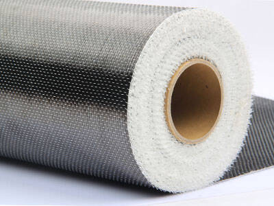
Tejido de fibra de carbono unidireccional de alta resistencia para refuerzo de compuesto de polímero reforzado con fibra (FRP).

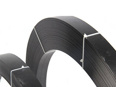
Imprimación de fibra de carbono de baja penetración y alta penetración para superficies de concreto reforzado

Impregnación y pasta de componentes reforzados de superficie y productos de fibra.
