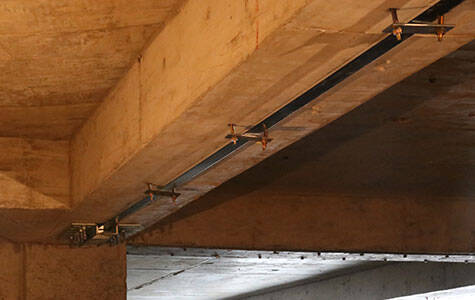
Refuerzo de vigas
Laminados de CFRP y láminas de CFRP
The final scheme is that all the beams of the building are strengthened by carbon fiber reinforced polymer(CFRP) laminates, and the inclined section is strengthened by carbon fiber reinforced polymer(CFRP) sheets.

Proyecto
Debido a la renovación de los equipos de producción y al aumento de la carga útil del suelo y de los equipos, la capacidad portante original del edificio industrial es insuficiente, por lo que es necesario inspeccionar y reforzar los componentes portantes inferiores. El plazo de construcción es muy ajustado y las condiciones de construcción son deficientes.
En combinación con la evaluación del hormigón del proyecto, y atendiendo a los deseos de la Parte A, se utilizó CFRP para reforzar la viga del piso F2. Sin embargo, durante las pruebas y el análisis, se observó que la capacidad portante de la mayoría de las vigas del edificio es bastante diferente, y se requirió un mayor número de plantas para reforzarlas con más capas de láminas de CFRP. El esquema final consiste en reforzar todas las vigas del edificio con laminados de fibra de carbono, y la sección inclinada con tejido de fibra de carbono. El diseño y la construcción del proyecto avanzaron sin contratiempos, y se tomaron muestras de las vigas de refuerzo 7 días después de la finalización de la obra. Se realizó una prueba de sobrecarga in situ bajo la carga aplicada, sin detectar ninguna anomalía. El proyecto lleva medio año en funcionamiento y se encuentra en buen estado.
Estudio del refuerzo y propiedades del laminado y la lámina de CFRP
El edificio es una estructura de armazón, con una separación entre columnas de refuerzo de 6 m y una superficie aproximada de 1100 m². El número de vigas principales y secundarias es elevado: el grado de resistencia del hormigón en el diseño original es C25, y la barra de tensión es de grado II. Antes del refuerzo, se realizó una prueba exhaustiva del grado de resistencia de las vigas de hormigón armado, que resultó ser inferior a C25. En el diseño del refuerzo se utilizó C20. La capacidad portante de todas las vigas en el plano se verifica utilizando la cantidad de refuerzo proporcionada por el plano original. Se requieren 45 y 29 vigas para reforzar.
Laminado de fibra de carbono de 1,2 mm
Laminado de fibra de carbono HM-1.2T.pdf
Tejido de fibra de carbono de 230 g
Envoltura de fibra de carbono HM-23.pdf
Puntos clave de la construcción de laminados y láminas de refuerzo de CFRP
La tecnología de construcción del refuerzo de CFRP es relativamente simple, pero el proceso de construcción es más riguroso y la calidad del personal de construcción es mayor. Solo garantizando un halo de calidad de construcción se puede lograr el efecto de refuerzo esperado.
Los pasos principales son:
Tratamiento de la superficie del hormigón;
Tratamiento de nivelación;
Cepillo de la resina subyacente;
Adhesión del laminado de fibra de carbono;
Tratamiento de protección;
Hay dos puntos que requieren especial atención en la construcción.
(1) La interfaz debe manipularse correctamente; de lo contrario, afectará directamente la resistencia de la adherencia. La superficie del hormigón debe pulirse cuidadosamente con herramientas especiales, limpiarse con acetona, y las esquinas de las láminas deben compactarse estrictamente formando arcos y tratarse con materiales lisos.
(2) Al instalar el CFRP, las placas deben limpiarse con un paño y el aglutinante debe cepillarse uniformemente. Una vez pegado, utilice un rodillo especial para rodar hacia adelante y hacia atrás y asegurar que no queden grumos. Además, el proyecto consiste en una nave industrial con una temperatura máxima de 60 °C y una capa protectora de 2,5 mm de espesor de mortero M5 mezclado con cola sobre la superficie de fibra de carbono.
Inspección y aceptación
Para garantizar la seguridad y la fiabilidad de la estructura de ingeniería, se verifican estrictamente los criterios de inspección y aceptación. Además de la supervisión in situ durante todo el proceso de construcción, se probaron las propiedades mecánicas de los materiales de refuerzo y se seleccionó una viga de refuerzo típica LL 2 7 días después de la finalización del refuerzo.
Dada la complejidad de la transferencia de fuerza entre la viga principal y la viga secundaria, no es fácil analizar la fuerza. La viga L-2 seleccionada es una viga secundaria en tres partes de la placa, con ejes 21, 22, A y 1/B, rodeada por 6 m x 6 m. La carga se transmite directamente desde la superficie de la placa.
La viga probada tiene una longitud de 6 m, una superficie de apoyo de 12 m², una carga viva del suelo de 7 kN/m², una carga local del equipo de 117 kN en el centro de la viga y una carga total de 201 kN. La carga se aplica en obra, añadiendo 10 kN en cada nivel, simulando la distribución real de la carga y el apilamiento de la bolsa. Se miden la deformación en altura y la relación f(0,01 mm)-deflexión de la sección central del tramo de la viga bajo cada nivel de carga. Se observa la variación de la viga y la aparición de grietas. Al cargar a 180 kN, se observaron pequeñas grietas con el instrumento de observación de grietas, invisibles a simple vista. No se observaron cambios significativos al cargar hasta 201 kN. Existe una relación lineal entre la carga y la deflexión durante todo el proceso de carga. Con una carga de 201 kN, la deflexión medida es mucho menor que la deflexión admisible de la viga. Los cinco
Las galgas extensométricas fijadas a la altura de la viga se mantuvieron intactas. El diagrama de deformación dibujado bajo cada carga se ajusta básicamente a la ley de deformación de la sección plana, lo que demuestra que el laminado de fibra de carbono y el hormigón trabajan juntos y que la interfaz entre ellos está bien adherida.